Related Product
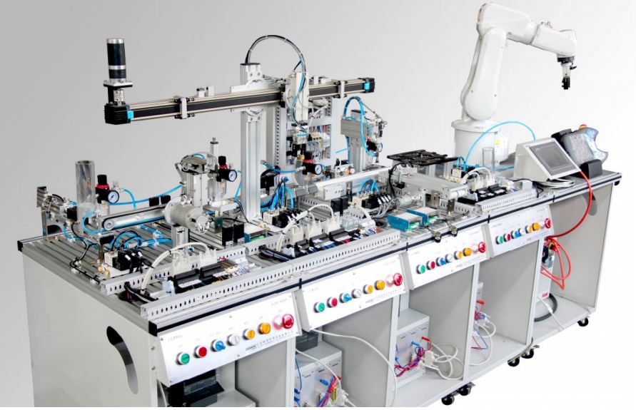
Industrial Product Line Training System with Robotic Manipulator
Model: LA-IMPT-I
Equipment Description:
The device is focus on Industry 4.0 development of vocational education, which is based on systematic job flow system solutions, it is comprehensive application reflect of Internet + industrial robot, Sensor, PLC control technology, smart electromechanical equipment and other technology. Therefore, it has also become World Skills mechatronics, required professional Equipment.
On automatic line always use sensor technology, electrical technology, and control technology, servo driven technology, just like human’s Sensory system, sport system, brain and nervous system. Then use this automatic line as vector to state above key technology as following
Equipment working principle :
Work piece in stock bin supplied in sequence, once detected work piece in place, pneumatic swing cylinder put material block into second
handling station.
Working process of handling station: when work piece come from last station, actuator moves to the left slug crawling position, vertical
cylinder down, down in place, the air fingers crawl, crawl
into place- actuator moves to the right position > discharge gas release your finger > wait for the next vertical cylinder rising feed, single
station comprising qualified and unqualified silo, used as sorting material.
Working process of assemble station: Tag containing billets, after detecting sensor distinguish the color and texture of the material block,
waiting at the cylinder block material, color and texture
through the lid # 1 transmission belt and transmission belt sensor 2 # tell the difference, after a stretch a cylinder and a vacuum chuck
mounted on the Tag into billets by belt conveyor to the storage station.
Working process of handling and stacking station: After gob handling over, according to the different colors and materials of processed
material blocks to classification storage.
Main Technology Parameter:
(1.) Cabinet main circuit power supply: single-phase AC220V plus-minus 10%, 50Hz
(2.) Robot Model ANNO-602 Robot Equivalent to IRB120 / 3KG / 0.58
-integrated source: 10 Road; integrated gas source: 4;
-repeat positioning accuracy: 0.01mm;
-degree of protection: IP30;
-rotation axis working range + 165 degree ~ -165 degree
-maximum speed of 250 degree / s;
-2-axis arm operating range +
-110 degree ~ -110 degree maximum speed of 250 degree / s;
-3-axis arm for the range of + 70 degree ~ -90 degree
-Maximum speed of 250 degree / s ;
-axis 4 wrist operating range + 160 degree ~ -160 degree
-maximum speed of 320 degree / s;
-bending axis 5 working range of + 120 degree ~ -120 degree maximum speed of 320 degree / s;
-shaft 6 flip working range + 400 degree ~ -400 degree
-maximum speed 420 degree / s;
-1 kg Picking beat :25 x 300 x 25mm,
-0.58TCP maximum speed, 6.2m / s TCP acceleration of 28m / s,
-acceleration time 0-1m/ s2 0.07s Supply Voltage: 200-600V, 50 / 60Hz;
-Power : 0.25kW;
-robot base size : 180 x 180mm;
-height of the machine 700mm;
-robot weight: 25kg;
-outside with Device Net module
(3.) Cabinet control circuit power supply: DC24V (Maximum)
(4.) Temperature: -10 ~ 40 ; Humidity: degree C Less Than or Equal 90% (25 degree C);
(5.) Single Station Dimensions standard table.
(6.) Air pressure: 0.4 ~ 0.6 Mpa
(7.) Machine capacity: Less Than or Equal 5KVA
Main Composition:
(1.) Distribution Station:
Function: Supply the work piece in stock bin in sequence, work piece in place, electrical cylinder put the waste into waste bin, put the
qualified material block into punch station.
Structural composition:
Aluminum basal plate, electric control cabinet, PLC hung box, Operation panel, Pneumatic cylinder, charging barrel, magnetic valves, Mini
cylinder, vacuum chuck, parallel lines Groove, I/O switch over Module, Air controller.
Main electrical components:
-Illuminated push button stop/start: LAY50-22D one open DC24V (or Equivalent)
-Button signs : 22 mm
-Fiber optic sensor amplifiers: 6 bets
-Fiber optic sensor Amplifiers: PNP DC24V
-The receiver transmitter (generator): PNP DC24V
-Dimension: minimum (Length x width x height)- 450mm x 790mm x 1260mm
(2.) Handling station :
Function: Qualified material block transmitted to feed opening port, electrical robot arm, put away the transmitted work piece, depth sensor
detect it, unqualified parts be transmitted in waste groove, qualified parts will be transmitted to next station.
Structural composition: Aluminum Basal plate. Electric control cabinet, PLC hung box, Operation panel, Belt conveyor machine and install
bracket, Punching cylinder device and all the external member, parallel lines groove and guide Rail, I/O switch over module, Air source
processor and Send receiver.
Main electrical element:
-Fiber amplifier : PNP DC24V
-Fiber cable: Electric Actuator
-Dimension : (Length x width x height) 450mm x 750mm x 1030mm
-Air source pressure : 0.4~0.6Mpa
(3).Assemble Station:
Function: Equip with TAG material block, distinguish color and material of the material block by sensor test area, wait in barrier cylinder
color and material of cover distinguished by sensor on the 1# convey belt and 2# convey belt put on material block equipped with a TAG by
extending cylinder and vacuum sucker.
Structural composition: Aluminum Basal plate, Electric control cabinet, PLC hung box, Operation panel, Electric unit install board, Vacuum
generator sucker port, Vertical cylinder bracket and
barrier block, Section for install and assemble, Air source processor, Connect bracket between station and station, Solenoid valve, I/O switch
over module, Belt conveyor install bracket and cover guiding arc module,
Main electrical element:
-Inductive sensor: PNP or NPN, DC24V
-Fiber amplifier: PNP DC24V
-Signal generator: PNP DC24V
-Intermediate relay(with handle): 2 open 2 close DC24V
-PLC controller : suitable as per station
-Switch power supply: 24V 5A
YingbinAve,WeichengDistrict,Xianyang,
Shaanxi,China.
咸陽市渭城區迎賓大道中國陝西
Web: www.labasia.tech
Tel:+86-165320291781
Enquiry: sales@labasia.tech
-D type plug: AC220V 10A
-Dimension: (Length x width x height)= 450mm x 750mm x 1150mm
Industrial robot handling station and classified storage:
Function: Industrial robot according to different color and material of processed material block to classified storage.
structural composition: Aluminum Basal plate, Electric control cabinet, PLC hung box, Operation panel, parallel lines groove and guide rail,
I/O switch over module, Air source processor, Slope bracket and slope slide groove, Robot controller, Robot teaching units, Robot I/O extend
plate, Solenoid valve, Teach screen install plate.
Main electrical element:
-Fiber sensor: BF3RX PNP DC24V or equivalent
-Fiber cable: E32-DC200-6FD
-Signal generator: MBS5M-TDT1 PNP DC24V
-Intermediate relay (with handle): 2 open 2close DC24V
-Gray cable groove: 3030
-Aluminum guide rail: DIN35mm
-Touch screen: MCGS 7062k
-D type plug: AC220V 10A
-Training project: Industrial robot handling station control training, classified storage station control training, Touch screen and
communication control training.
Dimension: (Length*width*height)= 900mm*900mm*1110mm
Air source pressure : 0.4~0.6Mpa
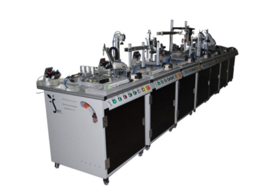
Industrial Automation Training System
Model: ZF-MTS902
General descriptions:
With 6 stations modular production system, mechatronics training includes distributing testing, processing, handling, assembly and storing stations that can be operated separately or integrally. The modular production systems allow varying simulation of real production processes that exist in industry field. The system is universal, industry based, modular and flexible for further expansion. Students can learn the entire process of production such as feeding, processing, etc. Each stations simplifies the training of operation and can be expanded sequentially step by step through building complete automated procedure.
Learning contents:
- Sensors
- Mechanical automation
- PLC program development
- Sequential control
- Installation diagnostic
- Pneumatic
- Drives
- Electronics
- Industrial safety
A. Distributing Station: A double-acting air cylinder pushes work pieces out individually. The cylinder is integrated into a work piece feeding module, cylinder and gravity feed magazine included. This feeder can carry up to six cylindrical work pieces. With a through-beam fiber optic sensor, it can monitor whether the work pieces is placed in the proper position. The handling arm module consists a rotary air cylinder and a mechanism. It moves the work pieces to next station. Two proximity switches detect the positions of the rotary cylinder. Various actuators used in this stations are industrial components. The following modules and components are included.
ZMP1104 - Pneumatics Training System
Feature:
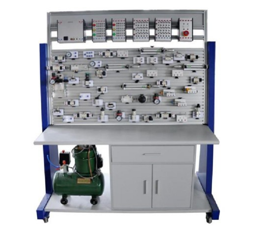
Pneumatic training device is at the request of modern pneumatic professional teaching experiment, according to “the hydraulic and pneumatic transmission ", "The Pneumatic control technology", etc., general teaching material contents design. The system in Addition Meet the base and teaching training system of need of practical applications Equipment structure is firm and has good stability Low noise operation layout clear and intriguing design The four truckle with crack slot in order to move and install on the work table. Panel grooves intervals are 25 mm, can easily move all kinds of components insert on it. Various pneumatic components into separate module which is equipped with bottom panel of elastic pins, when training they can build all kinds of pneumatic circuits on general aluminum, fast loading and unloading, flexible layout, clear pneumatic circuit Electrical control units used for independent relay control unit and multi-button unit control electrical, simple and clear! High safety: have over-current protection, the power supply will cut off as earth leakage exceed 30mA; the electrical control use DC 24v power supply, with over current protection, can prevent damage to the equipment caused by improper operation .system nominal pressure is 0.6MPa
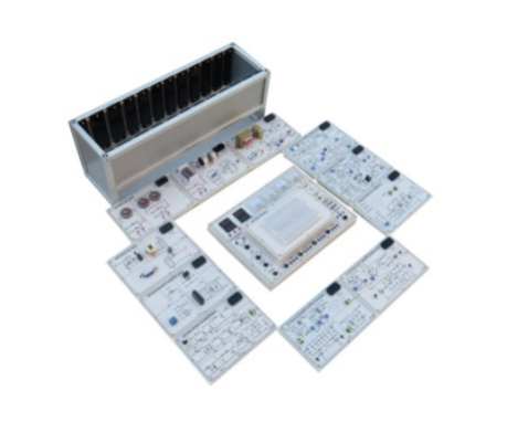
Advanced Sensor Experimental System
Model: SS1102C
Features:
Industrial-standard sensors and transducers With USB interface Open-ended design, ideal for expansion Offer a sensing data acquisition software Specification
Sensor Main Unit
1. Power Supply Unit
Fixed DC power supply
(1) Output voltage : +5V, -5V, +12V, -12V
(2) Max. output current : +5V/3A, -5V/0.3A, +12V/1A, -12V/0.5A
(3) With output overload protection
2. A/D Converter : 1x12-bit ADC
(1) Input voltage range : 0 ~ +5V
(2) Time pulse frequency : 3.58MHz
(3) Control signals : status, pole, over range indication
3. Interface Port USB interface : type B
4. D/A Converter : 1 x 12-bit DAC Analog output& control OUT+ : +DC OFFSET 0 ~ +4.096V unipolar OUT- : -DC OFFSET 0 ~ - 4.096V unipolar OUT BP : DC OFFSET -2.048V ~ +2.048V bipolar
5. Preset Level : 4-digit thumbwheel switch, Max. value : 4095
6. Status Display & DCV Input voltage measurement (1) Range : 2000mV, 20V (2) Accuracy : ±0.05% of reading + 4 counts (3) Input impedance : 10M ohms (4) Display : 4 1/2 digits
7. Mode Selector : manual/single-chip
8. Buzzer : Max. input signal voltage : +12V .
9. Micro Controller Signals : 5 control line outputs
10. Model Holder : X4
11. Potentiometer : 100K ohms B-type
12. Comparator : V-, V+ input, Vo output
13. Differential Amplifier : V-, V+ input, Vo output
Basic Sensor Experimental System
Model: SS1102D
Features
Industrial-standard sensors and transducers With USB interface
Open-ended design, ideal for expansion
Offer a sensing data acquisition software
Specifications:
Main Unit
1. Power Supply Unit
Fixed DC power supply
(1) Output voltage : +5V, -5V, +12V, -12V
(2) Max. output current : +5V/3A, -5V/0.3A, +12V/1.5A, -12V/0.3A
(3) With output overload protection 2. A/D Converter : 1x12-bit ADC (1) Input voltage range : 0 ~ +5V (2) Time pulse frequency : 3.58 MHz (3) Control signals : Status, pole, over range indication 3. Interface Port USB interface : Type B 4. D/A Converter : 1 x 12-bit DAC Analog output & control OUT+ : +DC OFFSET 0V ~ +4.096V unipolar OUT- : -DC OFFSET 0V ~ - 4.096V unipolar OUT BP : DC OFFSET -2.048V ~ +2.048V bipolar 5. Preset Level
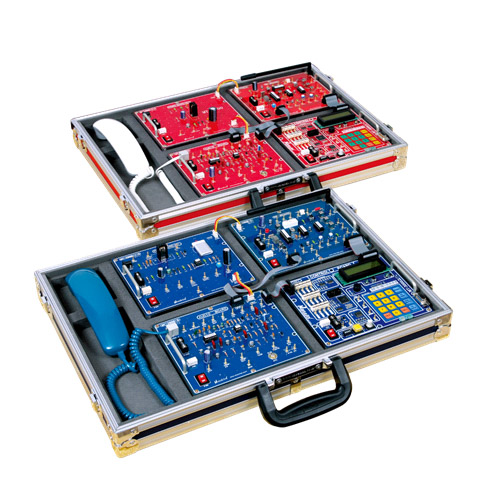
Mobile Communication Training System
LabAsia-Model: LA-MT-3000
Technical Specifications:
Ø Full Duplex Voice & Data Communication
Ø Half Duplex Voice & Data Communication
Ø Practice of RF interference & mobile environment
Ø Chatting by using Computer
Ø Board level and full system level experiment is
available using one set
Ø Auto Mode and Manual mode can be selectable
Ø Built-in Software equal to the Commercial Products
Ø Operating like as Commercial Mobile
Ø Products in Auto Mode
Ø 16 x 2 Character LCD
Ø LED Indicator
Ø Over Charge Protection
Ø Communication Method: Full Duplex / Half Duplex
Ø Channel Access: Multi Channel Access
Ø Frequency Range: Base 46.51 ~ 46.97 [MHz], Remote 49.67 ~ 49.99 [MHz]
Ø Output Power: +4.5 [dBm] Max
Ø Channels: 15 Duplex Channels
Ø Bandwidth / Channel: 25 [kHz]
Ø Modulation: FM
Ø Frequency Stability: 5 [ppm]
Ø Receiving Sensitivity: Over 20 [dB] SINAD (at -100 [dBm])
Ø Auto Channel Scan Time: 200 [ms]
Ø Data rate: 2,400 bps
List of Experiments:
Ø Board Unit Module Experiment: Power, Audio, Control, Radio Frequency.
Ø Half Duplex Audio and Data Experiment: Half Duplex Transmitting and Receiving Experiment.
Ø Full Duplex Audio and Data Experiment: Full Duplex Communication Experiment.
Ø Mobile Environmental Experiment: RF Interference Experiment among Systems.
Ø Data Communication: Chatting Practice by Serial Communication.
Training Contents:
Part 1. Introduction of Products:
Ø Experiment 1. Full Duplex Mobile Telecommunications Lab Equipment.
Ø Experiment 2. Power Part
Part 2. Audio Frequency Part:
Ø Experiment 3. Condenser Mike and Limiter
Ø Experiment 4. Compressor
Ø Experiment 5. Pre-emphasis and De-emphasis
Ø Experiment 6. Expander
Ø Experiment 7. Band-Pass Filter and Squelch Circuit.
Part 3. Radio Frequency Part:
Ø Experiment 8. PLL Oscillator
Ø Experiment 9. PLL Oscillator
Ø Experiment 10. Transmitting Part
Ø Experiment 11. Receiving Part
Part 4. Control Part:
Ø Experiment 12. Microcomputer and Key Matrix Control Peripheral Circuits
Part 5. Full Duplex Communication
Ø Experiment 13. Half-Duplex Transmitting Integration Experiment
Ø Experiment 14. Half-Duplex Receiving Integration Experiment
Ø Experiment 15. Full-Duplex Integration Experiment
Ø Experiment 16. Radio Environment Experiment
Ø Experiment 17. Chatting by using Serial communication
Components:
Ø Mobile Set: 1no
Ø Carriage Bag: 1 no
Ø Handset: 2 nos.
Ø Adapter: 2 nos.
Ø Base Set: 1 no
Ø Manual/Textbook: 1 no
Ø Program CD (Multimedia CD): 1 no
Ø RS-232C Cable: 2 nos.
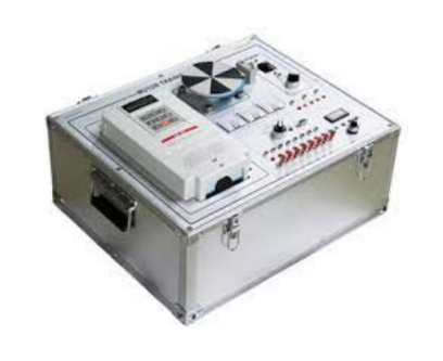
Inverter Experimental Trainer
Model: ST1116
Specification:
Output Characteristic ·
Max Output Voltage : 230V · Rating Output Frequency : Max 400Hz · Rating Output Ampere : 4.8A · Max Continuous Out Ampere : 5.4A · Output Capacity : 2.1 kw _ Power · Voltage & Frequency -3ǫ200/208/220V 50Hz -200/208/220/230V 60Hz · Allowable Voltage Fluctuating : 10% · Allowable Frequency Fluctuating : 10% _ Control Characteristic · Frequency Control Range : 0.1~400Hz · Frequency set Resolving Power -Digital : 0.01~0.1Hz, Analogic : 0.06/60Hz · Output Frequency Resolving Power : 0.01Hz · Frequency Setting Signal : DC 0~10V, DC 4~20mA · Accelerating & Decelerating Time : 0.1~6,000 Sec · Control Characteristic : Sine Wave PWM Type _ Protective Function · Motor Protective : Protective Terms of Electronic Thermal · Instantaneous Over Current : About 200% · Over Voltage : Main Circuit DC Voltage About 400V
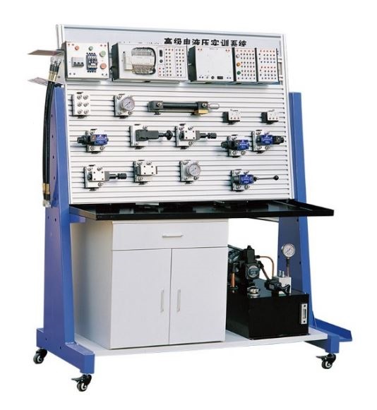
Basic Sensor Experimental Lab
Model: LA-BSEL-I
Technical Parameter :
Hydraulic operation station:
It consists of aluminum material profile,
Experiment table dimension : 1600(length)×750(width)×1780(height)mm
Aluminum panel dimension: 1200(length)×600(width)
Groove gap:25mm
Aluminum wood cabinet:1 piece
Caster with crack groove:4 pieces
Groove plate insert and extract system
Hydraulic components
Hydraulic pump station
(a). Work power: AC:380~400V
(b). Frequency: 50Hz
(c). Safety speed limit range: 1000-1500 r/min
(d). Power: 1.5KW
(e). Flow :6L/min
Electrical control module:
Power module: with three phrase leakage protection, output voltage:380V
Dc power module: output voltage DC24V
Rated current: 5A
Button module: signal light power: DC24V
Contact capacity AC220V/1A DC24V/2A
Machine electric life span: one million times
Relay module: coil voltage:DC24V;
Contact capacity:AC240V/10A/ DC24V/10A
Mechanism life: one million times
Proportion shuttle valve amplifier
Power: DC24V
Control voltage:±9V±2﹪
Max output current:1800Ma
Ramps time:0.02s-5s
Proportion relieve valve amplifier:
Power:DC24V
Rated current:800mA
Control range: DC0~+5V or DC0~+10V
Experiment contents:
Basic electric control
a) Lights on control
b) Lights out control
c) And logic control
d) Or logic control
e) Logic combination control
f) Relay self-lock control
g) The usage of proximity sensor
Hydraulic control circuit
1.Direction control circuit
a) manual shuttle valve reversing circuit
b) solenoid valve reversing circuit
c) lock circuit
2.Pressure control circuit
a)Single grade pressure regulating circuit
b) Secondary level pressure regulating
c) Single pressure reducing circuit
d) Level 2 pressure circuit
e) The unloading circuit using “M” “H” type manual shuttle valves
f) The unloading circuit using pilot relief valve
g) The balance circuit using the sequence valve
h) Liquid control one-way valve pressure maintenance.
i) The one-way back pressure circuit using relief valve
3.The flow speed regulator circuit using throttle valve
a) Enter oil-way throttle speed regulation
b) Back oil-way throttle speed regulation
c) Side oil-way throttle speed regulation
4.The speed regulator circuit using speed regulator valve
a) Enter oil-way throttle speed regulation
b) Back oil-way throttle speed regulation
c) Side oil-way throttle speed regulation
d) Speed synchronous circuit of the speed regulation valve
e) The parallel circuit of speed regulation valve
5.Fast moving circuit of hydraulic cylinder differential connection
6.Fast moving circuit of hydraulic cylinder differential connection
7.Sequence action circuit using sequence valve
8.Sequence action circuit use stroke switch control
9.Sequence action circuit use pressure relay control
10.One-way atresia circuit use hydraulic control one-way valve
11.Double-way atresia circuit use hydraulic control one-way valve
12. The lock circuit using O type shuttle valve
13.Relay control hydraulic basic circuit
Proportion hydraulic circuit experiment
1. Proportion amplifier principle
2. Proportion amplifier application
3. Magnetic proportion shuttle valve application
4. Hydraulic motor speed control
5. Hydraulic motor reversal control
Accessories:
– Hydraulic oil Compressor-01 no
– Connecting jack 2mm & 4mm : 01 Set
– Power Cable: 01 no
– PLC to PC Communication cable: 09 Sets
– Simulation software for compatible PLC
– English Manual & CD: 01 Set
Hydraulic Training System
Model : LA-HTS-I
Technical Parameter :
Hydraulic operation station:
It consists of aluminum material profile,
Experiment table dimension : 1600(length)×750(width)×1780(height)mm
Aluminum panel dimension: 1200(length)×600(width)
Groove gap:25mm
Aluminum wood cabinet:1 piece
Caster with crack groove:4 pieces
Groove plate insert and extract system
Hydraulic components
Hydraulic pump station
(a). Work power: AC:380~400V
(b). Frequency: 50Hz
(c). Safety speed limit range: 1000-1500 r/min
(d). Power: 1.5KW
(e). Flow :6L/min
Electrical control module:
Power module: with three phrase leakage protection, output voltage:380V
Dc power module: output voltage DC24V
Rated current: 5A
Button module: signal light power: DC24V
Contact capacity AC220V/1A DC24V/2A
Machine electric life span: one million times
Relay module: coil voltage:DC24V;
Contact capacity:AC240V/10A/ DC24V/10A
Mechanism life: one million times
Proportion shuttle valve amplifier
Power: DC24V
Control voltage:±9V±2﹪
Max output current:1800Ma
Ramps time:0.02s-5s
Proportion relieve valve amplifier:
Power:DC24V
Rated current:800mA
Control range: DC0~+5V or DC0~+10V
Experiment contents:
Basic electric control
a) Lights on control
b) Lights out control
c) And logic control
d) Or logic control
e) Logic combination control
f) Relay self-lock control
g) The usage of proximity sensor
Hydraulic control circuit
1.Direction control circuit
a) manual shuttle valve reversing circuit
b) solenoid valve reversing circuit
c) lock circuit
2.Pressure control circuit
a)Single grade pressure regulating circuit
b) Secondary level pressure regulating
c) Single pressure reducing circuit
d) Level 2 pressure circuit
e) The unloading circuit using “M” “H” type manual shuttle valves
f) The unloading circuit using pilot relief valve
g) The balance circuit using the sequence valve
h) Liquid control one-way valve pressure maintenance.
i) The one-way back pressure circuit using relief valve
3.The flow speed regulator circuit using throttle valve
a) Enter oil-way throttle speed regulation
b) Back oil-way throttle speed regulation
c) Side oil-way throttle speed regulation
4.The speed regulator circuit using speed regulator valve
a) Enter oil-way throttle speed regulation
b) Back oil-way throttle speed regulation
c) Side oil-way throttle speed regulation
d) Speed synchronous circuit of the speed regulation valve
e) The parallel circuit of speed regulation valve
5.Fast moving circuit of hydraulic cylinder differential connection
6.Fast moving circuit of hydraulic cylinder differential connection
7.Sequence action circuit using sequence valve
8.Sequence action circuit use stroke switch control
9.Sequence action circuit use pressure relay control
10.One-way atresia circuit use hydraulic control one-way valve
11.Double-way atresia circuit use hydraulic control one-way valve
12. The lock circuit using O type shuttle valve
13.Relay control hydraulic basic circuit
Proportion hydraulic circuit experiment
1. Proportion amplifier principle
2. Proportion amplifier application
3. Magnetic proportion shuttle valve application
4. Hydraulic motor speed control
5. Hydraulic motor reversal control
Accessories:
– Hydraulic oil Compressor-01 no
– Connecting jack 2mm & 4mm : 01 Set
– Power Cable: 01 no
– PLC to PC Communication cable: 09 Sets
– Simulation software for compatible PLC
– English Manual & CD: 01 Set
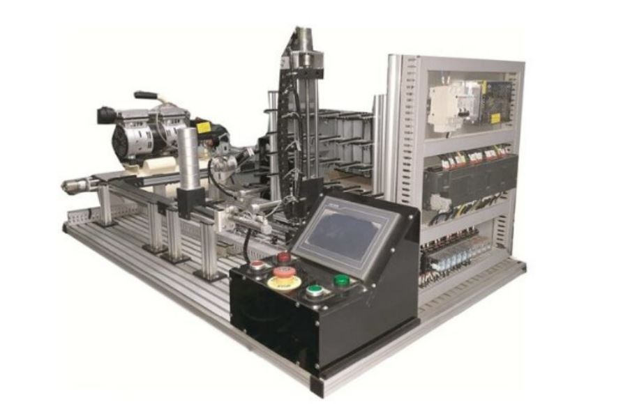
Automatic Storage and Sorting Trainer
Model:LA-ASST-I
Technical Parameter :
Base Plate: Aluminum
Function Start, Stop Switch & Emergency Switch
Conveyer Belt Size: 540mm – 560mm
Number of Conveyer Belt: 02 Set
Pneumatic Cylinder. 0 Pcs
Pneumatic motor: 01Pcs.
Capacity of motor: 0.15-0.7Mpa (Mega Pascal, Rotation:180°)
Optical Fiber Sensor:02 Nos
Magnetic Proximity Sensor:19 Nos
Solenoid Valve: 5 Nos
Warehouse Limit Switch: 21 nos
HMI: Display units of warehouse
HMI Display Size: 7 inch
Tray Movement 3 axis (X,Y,Z)
X-axis movement: 30 inch
Y-axis movement: 4.5 inch
Z-axis movement: 15 inch
Cabinet control circuit power supply DC24V ,3Amp
Temperature: 10-40: Humidity: ≤90%
Air pressure: 0.4-0.6Mpa
Machine capacity: ≤0.5KVA
Over Load Current Protection
Earth Lickage Protection
Input Power : Single Phase, Three wire AC
220v ±10%, 50.60Hz
PLC with Expansion Module :
Main Supply: Single Phase, 220v ±10%, 50.60Hz
PLC Input: 54
PLC Output: 10 Nos (Relay)
Analog Output: 02 Nos
Communication Port: 2 nos (RS-232)
PLC Output Relay Type
Operating Voltage: DC 24V
PLC Programming Language: Ladder , Functional Flow Block Diagram
PLC Software operating system: XP, Windows 7, Windows 8

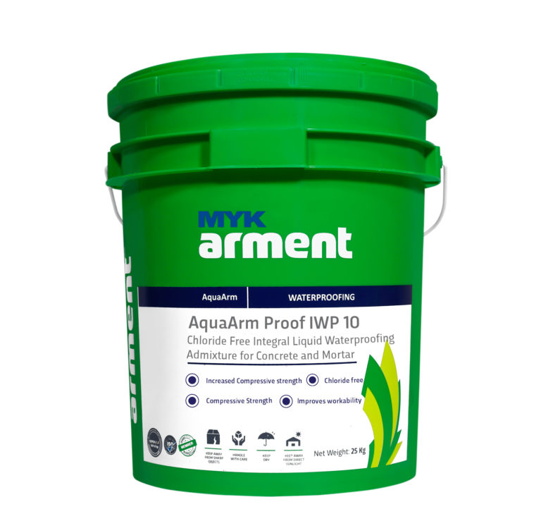
AquaArm_Proof-IWP-10
(Formerly known as MYK Proof WP10)
Chloride Free Integral Liquid Waterpro Admixture for Concrete and Mortar
AquaArm Proof IWP-10 is a chloride free liquid based on selected sugar reduced Ligno Sulphonates.
AquaArm Proof IWP-10 waterproofs by improving the quality of the Concrete or Mortar. It reduces the water demand for required workability and minimizes segregation and bleeding. It is in liquid form and shows excellent dispersion and is more efficient compared to traditional powder water proofers.